Lengthy deadtime adversely affects the PID control of any process. Knowing the process lag/deadtime ratio will tell how well (or not) a PID controller will work. Can your PID controller be a hero? See “Quick-start PID tuning tips to tune many controllers quickly” and 10 graphs to help.
Learning Objectives
- Learn how the lag/deadtime ratio tells how well a proportional-integral-derivative (PID) controller can respond to setpoint (SP) changes and reject process disturbances; higher controller gain speeds controller response to SP changes and reduces the effect of a process disturbance.
- Understand that PID control of a lag dominant process performs well and is easy to tune and that PID control of a moderate process can be effective if carefully tuned.
- Explore how PID control of a deadtime dominant process performs poorly and is difficult to tune. Adequate control may require process changes and/or advanced techniques. Quick start tuning tips and sanity check guidelines based on lag/deadtime ratio are provided.
PID controller-tuning insights
- In proportional-integral-derivative (PID) tuning, the lag time/deadtime ratio tells how well a PID controller can respond to setpoint (SP) changes and reject process disturbances; higher controller gain speeds controller response to SP changes and reduces the effect of a process disturbance.
- PID control of a lag dominant process performs well and is easy to tune and that PID control of a moderate process can be effective if carefully tuned.
- PID control of a deadtime dominant process performs poorly and is difficult to tune. Adequate control may require process changes and/or advanced techniques. Quick start tuning tips and sanity check guidelines based on lag/deadtime ratio are provided.
The lag-time-to-deadtime ratio of a process will determine if or how well a proportional-integral-derivative (PID) controller will work. Lag time is the time for the process to get to 63.2% of the final (steady state) response after the process starts moving. Deadtime is the time between when a correction is applied and the process starts to respond. In PID spotlight part 3 we split self-limiting processes into three general groupings based on the process lag (T1) to deadtime (Dt) ratio. The groupings were:
-
Lag dominant: T1/Dt > 4:1
-
Deadtime dominant: T1/Dt < 1:4
-
Moderate: 4:1 > T1/Dt > 1:4
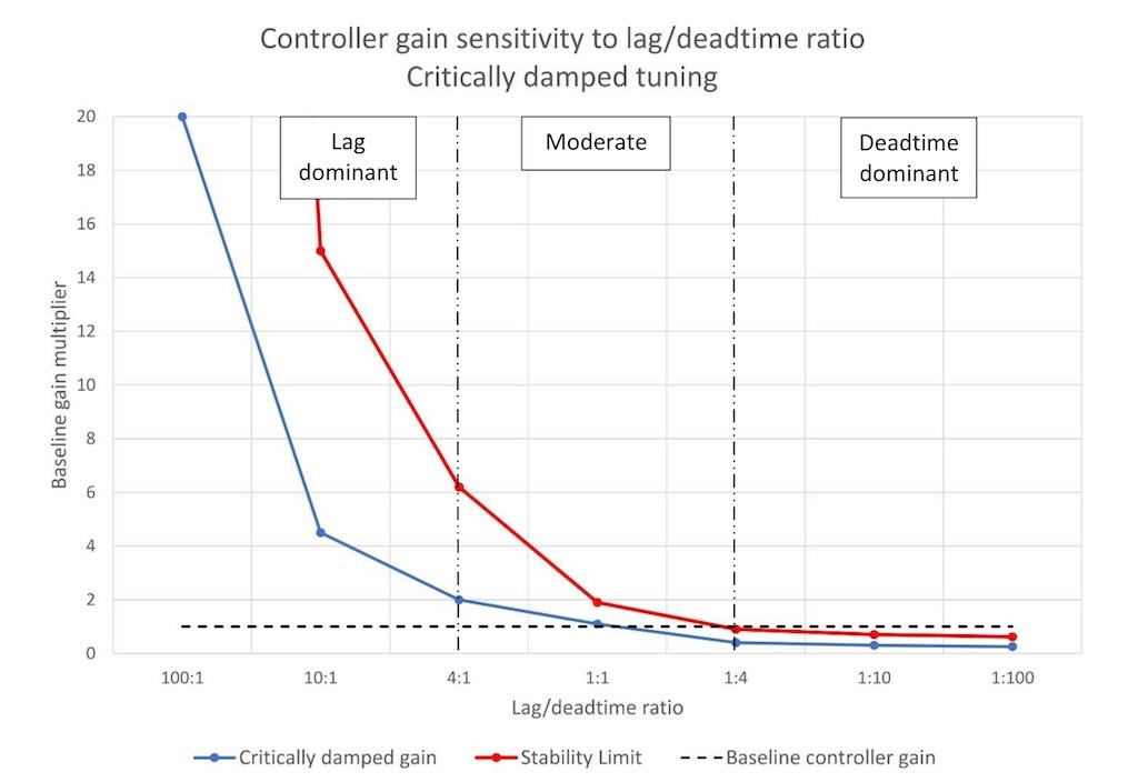
We gave a peek ahead in PID spotlight part 3, explaining that PID controller tuning in each of these groupings would be different. Figure 1 provides a quick visual overview of how controller gain differs with lag/deadtime ratio.
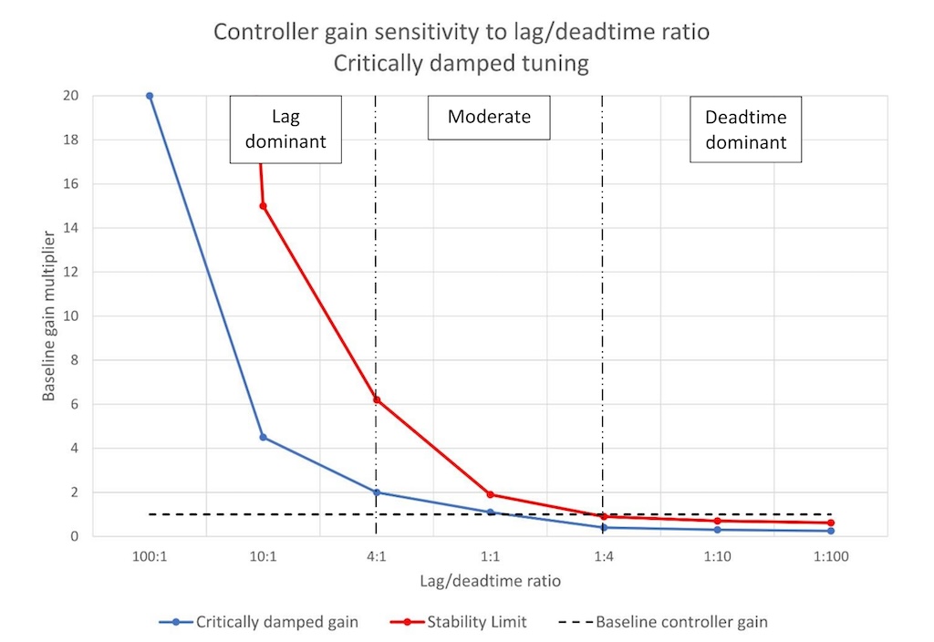
Figure 1 shows that as deadtime comes to dominate the self-limiting process response the maximum stable controller gain decreases (red line), which limits the effectiveness of a PID controller. Figure 1 also shows that the controller gain (blue line) for a critically damped controller response decreases proportionally to the stability limit. (The line for disturbance rejection tuning will be about 25% above the critical damping line.)
Before proceeding here are a couple of important definitions (PV is the process variable and OP is the controller output):
Baseline controller gain is the inverse of the process gain.
Kbase = 1/Kp
Where:
Kp = ΔPV/ΔOP (%/%)
Open-loop tuning methods calculate controller gain based on baseline controller gain and a multiplier based on process lag and deadtime. As you can see from figure 1 the multiplier will be greater than one when the lag time exceeds the deadtime and less than 1 otherwise (see the “baseline controller tuning” line in Figure 1). We can (and will) use this knowledge to help guide our tuning efforts, especially when we are under a time constraint.
A closer look at lag/deadtime ratio
Controller gain is our primary knob for controlling speed of response to setpoint (SP) changes and for controlling disturbance rejection. If we can make controller gain larger without going unstable, we can get faster response to SP changes and better disturbance rejection.
Figure 1 tells us that:
-
Lag dominant processes are easy to tune and control.
-
Moderate processes can be controlled with careful tuning.
-
Deadtime dominant processes will be difficult to tune and control.
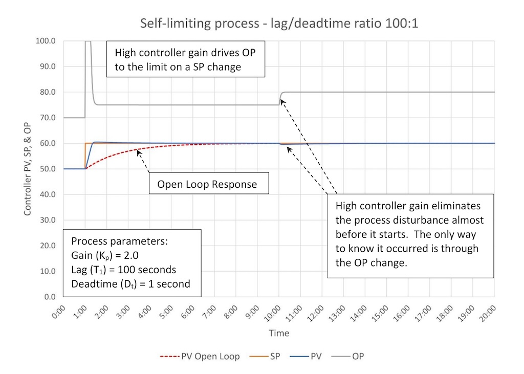
Figure 2a shows the response of a highly lag dominant process (lag/deadtime ratio 100:1). The process gain (Kp) is 2.0, which makes the baseline controller gain (Kbase) = 0.5 (the inverse of 2.0). (A process gain of 2.0 is used in all following examples for consistency.)
As we expected since the lag/deadtime ratio is very high this controller:
-
Moves the PV to SP very quickly after a SP change, especially when compared to open loop response.
-
Eliminates a 10% disturbance at the 10-minute mark with almost no visible impact on the PV. About the only way to know a disturbance occurred is the OP moved to correct the disturbance.
-
Is very easy to tune. The gain could have been increased considerably (I just stopped at 10. The controller went unstable at a controller gain just under 50.)
The one disadvantage is the high controller gain causes the OP to hit a limit on any but the smallest of SP changes. This may be a problem for downstream processes. The easiest solution is to reduce controller gain, but this will allow any process disturbance that happens to cause a larger and more persistent PV deviation from SP.
If this is not acceptable you can consider using advanced PID options such as integral only on SP change, SP ramping, OP rate limits and (most effective) a SP filter. Figure 2b shows the response of the same controller with a SP filter applied.
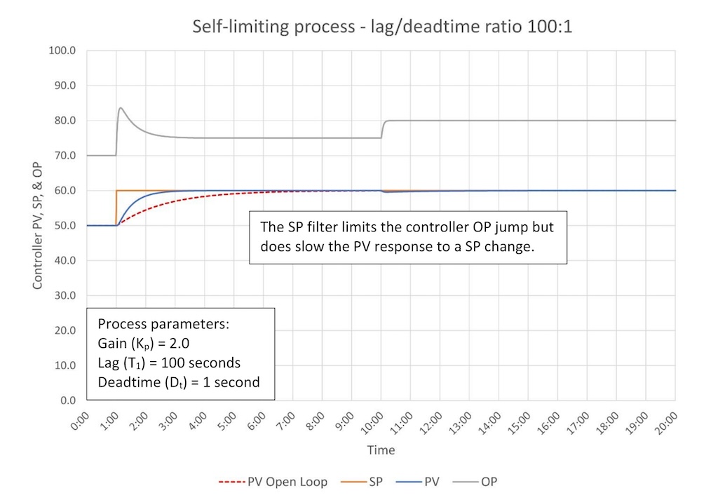
A SP filter allows you to tune the controller response to balance the approach of the PV to SP against the aggressiveness of the OP response. More filtering limits the aggressiveness of the OP response, but slows the rate at which the PV gets to SP. Note that the controller response to a disturbance remains just as effective.
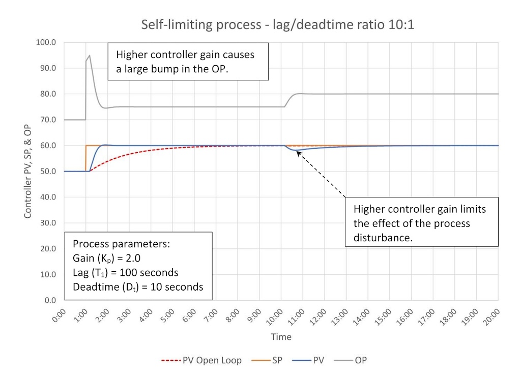
Figure 3 shows the response of a more typical lag dominant process (lag/deadtime ratio 10:1). As expected, since this is a lag dominant controller, we see:
-
The PV moves to the SP very quickly after a SP change relative to the open loop response.
-
The 10% disturbance at the 10-minute mark has a limited (2%) impact on the PV.
-
This controller is still easy to tune as critically damped tuning is far from the controller stability limit.
We still have the problem of aggressive OP movement on a SP change, which can be managed as suggested above.
When the process has multiple lags, consider this
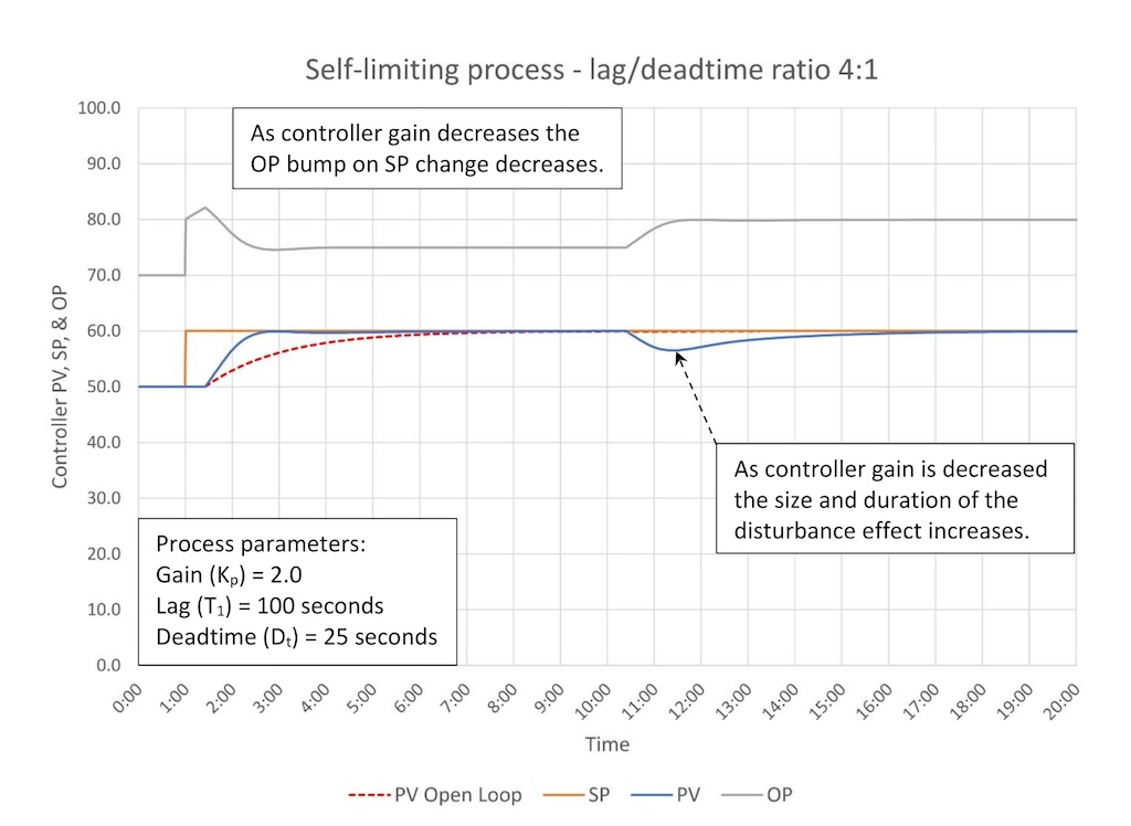
Figure 4 shows the response of a borderline lag dominant/moderate process (lag/deadtime ratio 4:1). This is tuned without derivative, however, in these borderline cases derivative might be useful if the process has multiple lags (this one does not).
We can see that controller tuning and what it can do for us is changing:
-
The controller can still get the PV to SP faster than open-loop response after a SP change.
-
The size and duration of a process disturbance increases relative to higher lag/derivative ratio processes. A 10% disturbance is limited to about a 3-4% PV disturbance.
-
Controller stability limits how aggressively we can tune the controller.
OP movement on a SP change still exceeds the final OP movement, but is limited and much less likely to be a problem for downstream processes.
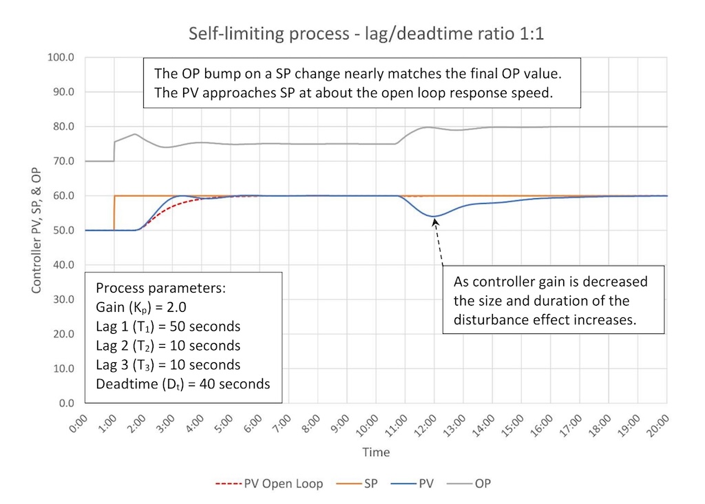
Figure 5a shows the response of a “dead center” moderate process (lag/deadtime ratio 1:1). Two secondary lags have been added to permit the use of derivative. Figure 5b show how to spot when secondary lags exist.
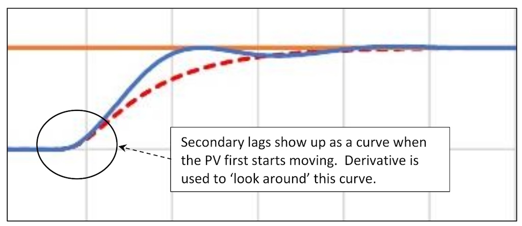
In addition to adding a curve to the front of a process response, secondary lags also add deadtime. While programmed deadtime is 40 seconds effective deadtime is 50 seconds.
Controller gain is now down to 0.55, barely larger than the baseline controller gain (0.5). At this point the ability of a PID controller to control this process begins to get limited:
-
The controller can get the PV to SP only slightly faster than open-loop response after a SP change.
-
The size and duration of a process disturbance is now significant relative to the size of the disturbance. A 10% disturbance creates about a 5% PV disturbance.
-
Controller stability limits constrain how aggressively we can tune the controller.
At this point OP movement is constrained by controller tuning and has little possibility of disturbing downstream processes.
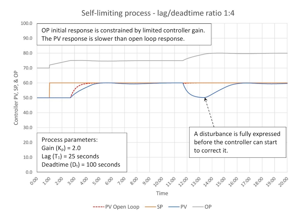
Figure 6 shows the response of a borderline moderate/deadtime dominant process (lag/deadtime ratio 1:4). The controller gain is 0.2, which is now less than the baseline controller gain (0.5).
Deadtime is now limiting what this controller can do:
-
The controller will go unstable if the baseline controller gain is used. Integral now must do most of the work to get the PV on SP.
-
The controller cannot get the PV to SP faster than open-loop response after a SP change. This is because the controller gain is not larger than the baseline controller gain (baseline controller gain is the minimum controller gain required to match open-loop response).
-
A process disturbance will be fully expressed before the controller can start to eliminate it. A 10% disturbance results in a 10% PV disturbance.
OP movement is limited and mostly consists of integral action slowly working to eliminate the error.
PID options: Fixing a typical deadtime dominant process

Figure 7 shows the process response of a typical deadtime dominant process (lag/deadtime ratio 1:10).
Deadtime is now seriously limiting what the controller can do:
-
The controller will go unstable if the gain matches the inverse of the process gain. Integral now must do most of the work to get the PV on SP.
-
On a SP change the PV response considerably lags the open loop response.
-
A process disturbance will be fully expressed and persist before the controller can start to eliminate it. In this case a 10% disturbance results in a 10% PV disturbance that persists for 1.5 minutes before the controller can start to eliminate it.
OP movement is limited and mostly consists of integral action slowly working to eliminate the error.
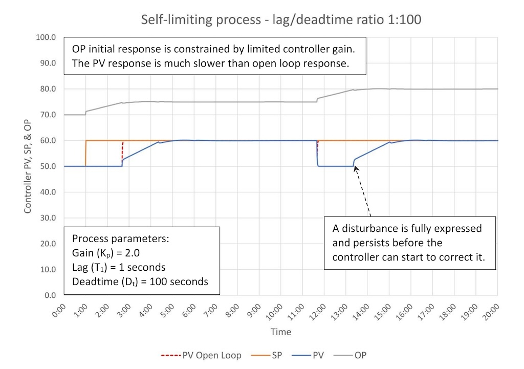
Figure 8 shows the response of a self-limiting process that is extremely deadtime dominant (lag/deadtime ratio 1:100). This is the functional opposite of figure 1. Whereas a heavily lag dominant process (100:1) is extremely easy to control a heavily deadtime dominant process is extremely difficult to control. It is not possible to get reasonable (compared to open-loop) PV response to a SP change and disturbances will linger for the duration of the deadtime before the controller can start to correct the disturbance. It will take another full deadtime before the disturbance is eliminated.
Tuning a deadtime dominant process is difficult because the stability window is very small. Specific techniques for tuning deadtime dominant process will be discussed later, however to achieve better control you should first (in order):
-
Eliminate deadtime through process design changes (easiest in the process design stage).
-
Eliminate process disturbances by controlling the upstream process.
-
Compensate for disturbances using feedforward control.
If the above techniques do not provide adequate relief or are not possible there are advanced methods including:
-
Using an external reset PID with deadtime estimation logic.
-
Model-based control.
Key PID tips to overcome deadtime effects
Deadtime adversely affects the PID control of self-limiting processes.
We’ve seen that the higher we can set the controller gain the controller response to a SP change is faster and disturbance rejection is better. However, as deadtime increases relative to process lag (lag/deadtime ratio falls) the ability to turn up the controller gain is increasingly limited by stability. Deadtime makes a controller less stable, which limits how well a PID controller can control a self-limiting process.
In summary as the lag/deadtime ratio falls:
-
Controller gain is limited by stability.
-
PV response to SP changes gets slower.
-
Disturbance rejection gets worse, eventually to the point that disturbances are fully expressed and persistent.
-
Tuning the PID controller becomes more difficult.
Note that controller gain is not influenced by the process lag or deadtime individually; only the ratio. The controller gain will be the same if the lag is 100 seconds and the deadtime is 10 seconds, or if the lag is 100 minutes, and the deadtime is 10 minutes. (Integral is very much affected by the lag and/or deadtime.)
As you tune a self-limiting process keep these general guidelines in mind:
For lag dominant processes controller gain (K) can be set considerable larger than the baseline controller gain (Kbase) and integral (Ti) is nominally about equal to the primary process lag (T1). Derivative is not recommended.
K > Kbase
Ti ~= T1
For a moderate process controller gain (K) will be approximately equal to the baseline controller gain (Kbase) and integral (Ti) is nominally about equal to the sum of the primary process lag (T1) and deadtime (Dt). Derivative (Td) is generally set to one-fourth of integral.
K ~= Kbase
Ti ~= T1 + Dt
Td = 0.25 * Ti
For a deadtime dominant process controller gain (K) must be lower than the baseline controller gain (Kp) and integral (Ti) is nominally about equal to the process deadtime lag (Dt). Derivative is not recommended.
K < Kbase
Ti ~= Dt
These will provide a sanity check on any loop-tuning constants you may calculate.
Quick-start PID tuning tips to tune many controllers quickly
If you are in a startup situation and need to tune a lot of controllers very quickly, you can estimate conservative but serviceable tuning constants for most self-limiting processes using:
K = Kbase
Ti = T1 + Dt
This will provide stable but sluggish control for lag dominant and moderate self-limiting processes. This will be unstable for deadtime dominant processes, however, these are rare and usually easy to identify.
In future installments, I will discuss ways to make quick estimates of baseline controller gain, deadtime, and if the situation is right process lag without performing open-loop step tests. These may not be terribly accurate but will get you started. There are also default-tuning constants that can be applied to most flow and level loops. (Sorry, but pressures and temperatures will need some individual attention.)
Of course, after startup is complete you will return to properly tune these controllers.
Ed Bullerdiek is a retired control engineer with 37 years of process control experience in petroleum refining and oil production. Edited by Mark T. Hoske, editor-in-chief, Control Engineering, WTWH Media, [email protected].
KEYWORDS: Proportional-integral-derivative, PID tutorial, lag/deadtime ratio
CONSIDER THIS
What does the process lag/deadtime ratio tell you about the effectiveness of PID control?
ONLINE
Follow the Control Engineering PID series from Ed Bullerdiek, retired control engineer.
Part 1: Three reasons to tune control loops: Safety, profit, energy efficiency
PID spotlight, part 2: Know these 13 terms, interactions
PID spotlight, part 3: How to select one of four process responses
PID spotlight, part 4: How to balance PID control for a self-limiting process
PID spotlight, part 5: What does good and bad controller tuning look like?
