Inside Machines, Part 2: Using calculations and equations will demonstrate how to correctly size a rotary knife application based on previous data. Part 1 covered key terms.
Learning Objectives
- The key components of sizing a rotary knife include finding a cam relationship for the worst-case product to cut, knowing inertia of the cylinder to rotate and using software.
- Modifications can be added after confirming these critical items.
- A flywheel disk to mimic a rotary knife application case study is used.
Calculations and equations below can correctly size a rotary knife application based on previous data. As a side, the shortest cut length at the highest web speed is the worst case for this application, so that criteria is used in the sizing.
In a previous article, part 1 (Single blade rotary knife: Application overview) key terms were discovered to understand the rotary knife application. These include:
- Synchronous cut length
- Synchronous knife speed
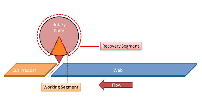
- Working segment
- Recovery segment
- Critical long length.
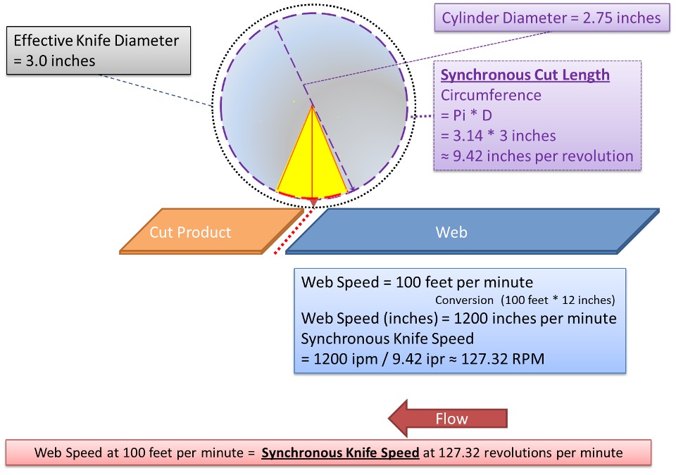
Synchronous cut length in high-speed motion control
The system is using one knife blade and the line speed requirement is 1200 inches per minute (20 inches per second). Now it’s time to focus on using a shortest product cut length of 4.71 inches. Please note, if more than one blade is being used in the application, the synchronous cut length will need to consider these blades. For example, if two blades are being used, use the following equation:
Equation 1) SCL = (Pi * D) / Nb
Where: SCL = Synchronous cut length
D = Diameter
Nb = Number of blades
Using the equation above, the synchronous cut length is:
- SCL = (Pi * 3) / 1
- Synchronous cut length = 9.42 inches
Working segment angle for high-speed motion control
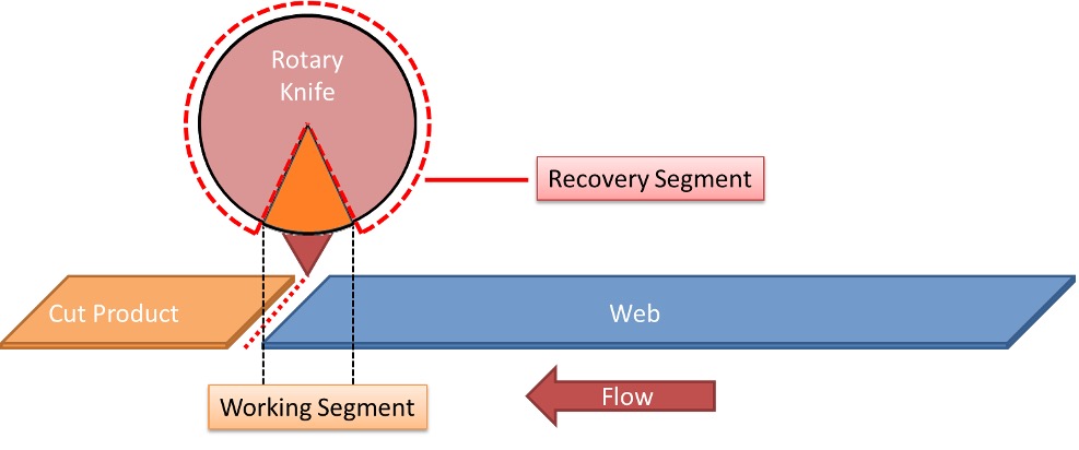
The working segment is the section where the actual cutting takes place during the portion of the rotary knife cycle. With 0 degrees being at the bottom of the rotary knife cycle, 5 degrees forward and 5 degrees behind is allocated for this working section. Therefore, a total of 10 degrees can be allotted which will equate to some amount of linear travel on the web.
Using a working segment angle of 10 degrees, the following equation 2 can find the linear distance travelled in the working segment (Synchronous angle):
Equation 2) LDT = WSeg / 360 * SCL
Where: LDT = Linear distance travelled in the working Segment
WSeg = Working segment (in degrees)
When using equation 2, the linear distance travelled in the working segment is:
- LDT = 10 degrees/360 degrees * 9.42 inches
- Linear distance travelled in the working segment = 0.2616 inches
Recovery segment angle for high-speed motion control
The recovery segment angle is the remainder of travel required by the rotary knife to prepare for the next cut. Or put another way, the portion of the cycle that is not synchronized; therefore, the need to speed up or slow down. This angle can be found by the following equation:
Equation 3) RSegAngle = (SCL – LDT ) * ((360°/NBL)/SCL)
Where: NBL = Number of Blades
Using Equation 3, the Recovery Segment Angle is:
- RSegAngle = ( 9.425 – 0.2618) * ((360°/1) / 9.425 inches
- RSegAngle = 0 degrees
Using a recovery segment angle of 350.0 degrees, the following equation 4 can find the linear distance travelled within the recovery segment angle):
Equation 4) RSEG = SCL – LDT
Where: RSEG = Recovery Segment in distance units
Using Equation 4, the recovery segment is:
- RSEG = 9.425 inches – 0.2618 inches
- RSEG = 9.1632 inches
Step 1 – An electronic cam relationship
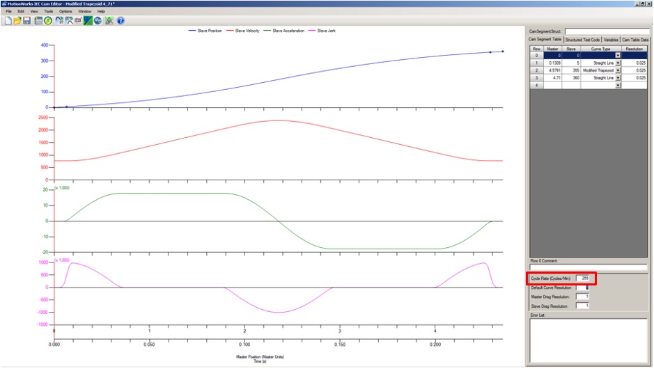
To present a relationship between the web and the rotary knife cylinder, an electronic cam table is utilized to find the main points throughout the cycle. This will offer a great motion profile to size the correct servomotor for the application. Since the shortest product cut length is 4.71 inches, the following table gives the main points of the segments for the electronic cam:

The following diagrams explain the four segments for this relationship:
Point 1

Since it is known the initial cut will begin at 0, the relationship for point 1 between web and rotary knife, respectively, is: 0,0.
Point 2
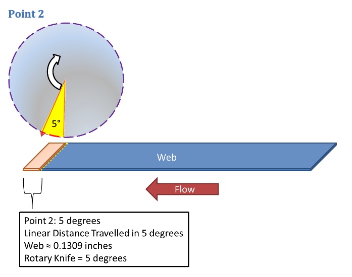
Knowing the LDT is 0.26 inches in the 10 degrees working segment, to find the LDT in 5 degrees, simply divide LDT by 2 to get 0.1309 inches for 5 degrees of rotation by the rotary knife.
Point 2 becomes 0.1309, 5.
Point 3
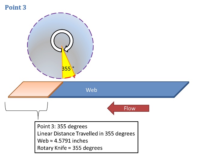
Continuing on with the RSEG at 355 degrees, the LDT will be 4.5791 inches of travel for the web. Therefore, point 3 becomes 4.5791, 355.
Point 4

Finally, point 4 becomes the shortest cut length at 360 degrees, which makes 4.71, 360.
Step 2 – Finding the rotary knife cylinder inertia
Using sizing software with the diagram and mechanical information below, users can find the inertia of any object needed for sizing.
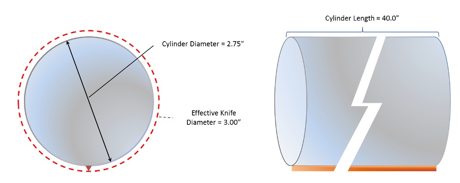
- Blade thickness: 1/8 inch
- Single knife blade
- Rotary knife cylinder dimensions:
- Outer diameter of cylinder: 2.75 inches
- Length: 40 inches
- Material: Solid steel
- Inertia: 0.01857 kg*m2

Note: If the rotary knife cylinder is hollow, include the inner diameter to find the correct inertia of the cylinder. Otherwise, the servomotor will be oversized and will increase in cost.
For the initial design, assume there is no gearing to get the actual torque and speed requirements for the application. Modifications can be added after confirming these critical items.
Step 3 – Motor sizing software and cam editor for servomotor sizing
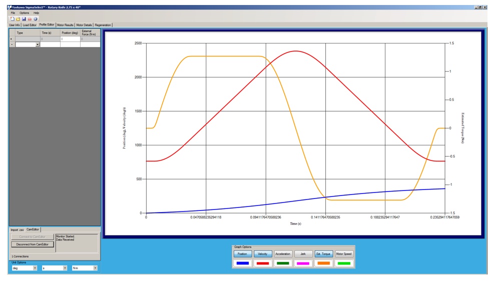
While finding the inertia of the rotary knife cylinder is advantageous, continuing onward within Yaskawa’s SigmaSelect servomotor selection software allows users to correctly size a servomotor for the application. Key screenshots detail how to use the inertia and camming relationship to allow for smooth motion on any rotary knife mechanical system.
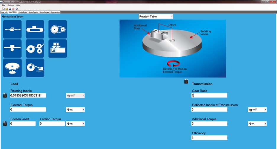
Notice the inertia of the rotary knife cylinder has already been entered in the “rotating inertia” entry.
Moving forward to the profile editor, it will be easier to implement the camming relationship discussed earlier. Yaskawa’s MotionWorks IEC 3 software allows users to enter cam points to create the motion profile best suited for system mechanics.
Opening Yaskawa’s MotionWorks IEC 3 software, found at www.yaskawa.com/iecsw, make use of the Use the software’s cam editing feature by entering in the electronic cam from step 1. The basic steps are:
- Enter the points for the web (master axis) and the rotary knife (slave axis)
- Pick the curve type
- Interface the two programs with the Yaskawa SigmaSelect Icon
Please pay attention to the cycle rate as it is based in cycles per minute and must match the correct motor rpm. This means the cycle rate is based off of the number of cuts per the shortest product cut length given a web speed. For this example, the web speed was calculated at 1200 inches per minute. With the shortest product cut length of 4.71 inches, the following equation will calculate the correct cycle rate number:
Equation 6) Cycle rate = Web speed/shortest product cut length
Using Equation 6, the cycle rate is:
- Cycle rate = 1200 ipm / 4.71 inches
- Cycle rate = 254.78, which can be rounded up to 255 cycles/minute
A straight-line interpolation is used for the cutting segment since it is a constant velocity, and the modified trapezoid interpolation is used for the recovery segment of the cam (though other interpolation types could be used).
Case study example for high-speed motion control
Using an actual flywheel disk to mimic a rotary knife application, the following mechanical information has been given:
- Single knife blade
- Rotary knife cylinder dimensions:
- Approximate outer diameter of cylinder: 2.75 inches
- Approximate length: 1.18 inches
- Material: Aluminum
- Inertia: 0.7252 kg*cm2
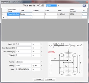
The sizing software has shown the Yaskawa Sigma-7 Series SGM7A-01 100-W servomotor has an inertia ratio mismatch of 21.5:1.

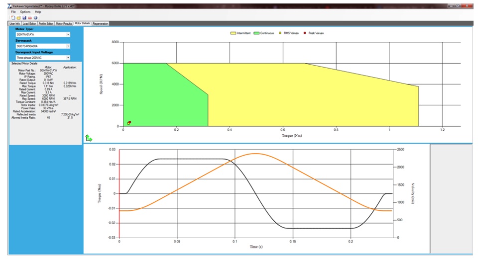
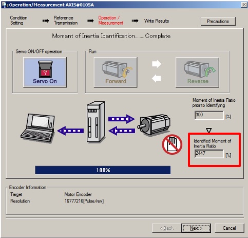
Using Yaskawa’s SigmaWin+ Version 7, servomotor setup software, see that the inertia ratio of the detected disk is very close to the sizing file at 24.47:1, given the exact mechanical disk:
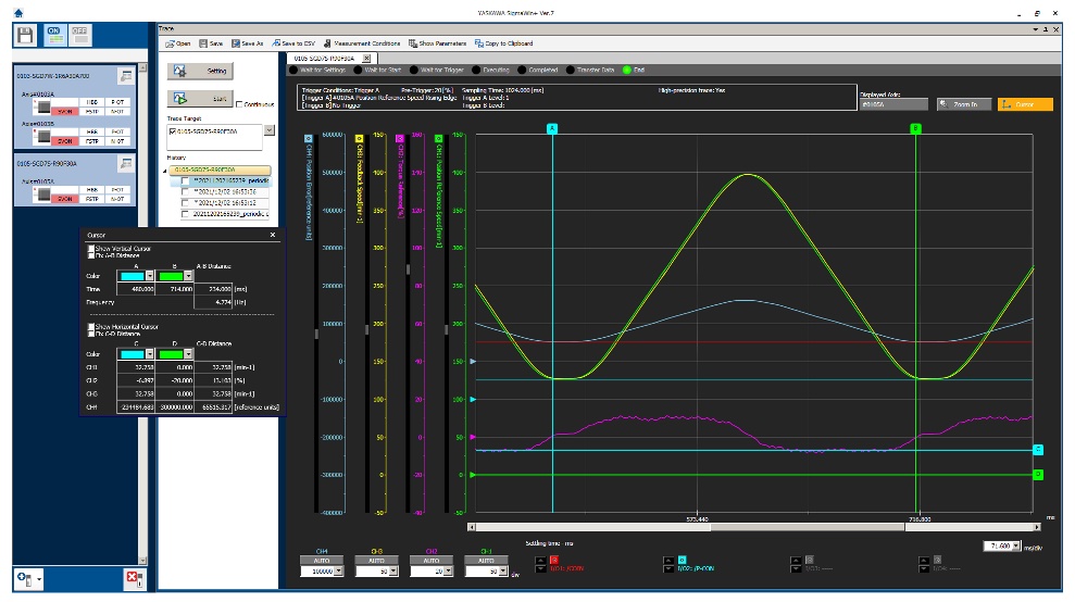
Within SigmaWin+ Version 7, the cam profile is shown verifying the calculations above:
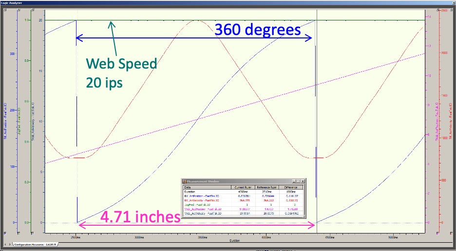
Within MotionWorks IEC 3, the Logic Analyzer can verify the cut length is correct for one cycle of the rotary knife. The 4.71-in. cut is verified by using the pink curve and subtracting the end position of 9.3837 from the beginning position at 4.6709 and the cycle repeats if the cam continues to run at the web speed. The web speed is verified by the dark green line of 20 inches per second, which equated to 1200 inches per minute.
Sizing rotary knives for high-speed motion control
In summary, sizing a rotary knife isn’t difficult. The key components include finding a cam relationship for the worst-case product to cut, knowing the inertia of the cylinder to rotate and using software to ease the guesswork. In this way, a servomotor with enough torque, speed and inertia can be sized accordingly without having too much overhead.
Sixto Moralez is a senior regional motion engineer for Yaskawa America Inc. Edited by Chris Vavra, web content manager, Control Engineering, CFE Media and Technology, [email protected].
MORE ANSWERS
Keywords: rotary knife, CNC, motion control
ONLINE
See Part 1 motion control article on rotary knives linked below.
CONSIDER THIS
How could this information help your next high-speed motion control application?

