Part 2: Understand the advantages of 36-pulse input drive topology in medium-voltage (MV) motor applications and how medium-voltage VFD design mitigates harmonics and improves power quality.
Learning Objectives
- Review variable frequency drive (VFD) fundamentals and how a VFD works on the way to understanding how non-linear loads create power-quality concerns.
- Understand harmonic filtering and how a VFD can help.
- Examine medium-voltage 36-pulse drive topology and how it reduces risk of equipment malfunction by reducing harmonic stress.
Harmonic mitigation with 36-pulse VFD insights
- Variable frequency drive (VFD) fundamentals help when understanding how non-linear loads create power-quality concerns.
- VFD harmonic filtering can improve power quality.
- Medium-voltage 36-pulse drive topology can reduce risk of equipment malfunction by reducing harmonic stress.
Pumping, compressing, blowing, conveying, extruding and mixing are among most common industrial motor applications using variable frequency drives (VFDs). Understanding applications and drive design can help mitigate harmonics and power-quality challenges. As explained in part 1, when motors are started across the line on 60Hz utility power, efficient motor operation is limited to a very narrow window around the rated motor operating speed and torque values. Drives allow motors to operate at their optimal efficiency over a wide range of speeds, satisfying a wide range of varying torque requirements, while reducing motor stress and starting inrush current.
VFD fundamentals, how a VFD works
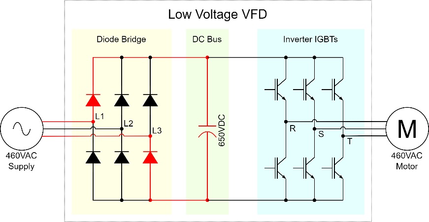
For every motor, the optimal supply voltage and frequency changes as the speed and torque requirements of the application change. When started across the line, a 460V 60Hz motor can only operate at the utility supplied voltage and frequency. Drives overcome this limitation by continuously adjusting the output voltage and frequency to match the optimal operating conditions for the application load. Most common low voltage (LV: less than 1000V) drives are comprised of three sections; power flows from left (utility supply) to right (motor) in Figure 1.
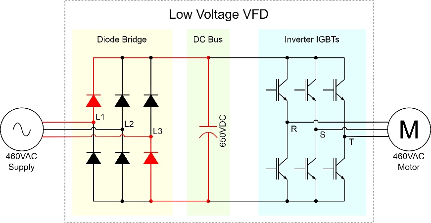
The diode bridge converts three-phase utility supply power from alternating current (AC) to direct current (DC).
The DC bus acts as a battery. The bus stores the energy it receives from the diode bridge until that energy is needed by the inverter section.
The inverter IGBTs (insulated-gate bipolar transistors) are switches that turn on and off at a very high rate of speed. By using pulse width modulation (PWM), the drive generates a series of short pulses and long pulses that, when averaged, are representative of a sine wave voltage waveform.
For more Control Engineering details and diagrams about the basics of medium-voltage drives, see: “How to choose a VFD for medium-voltage motors.”
How non-linear loads create power-quality concerns
Power quality concerns arise when non-linear loads are connected to an AC supply.
A load is considered linear when its impedance is constant, and the current waveform follows the sinusoidal supply voltage waveform. An electric resistance heater is an example of a linear load. When supplied by a 60Hz sinusoidal voltage, a resistive heater will draw a 60Hz sinusoidal current. Because the current is purely sinusoidal, linear loads have no high frequency harmonic content, and do not contribute to harmonic voltage distortion.
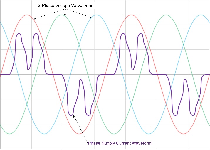
The diode bridge on a typical low voltage six-pulse drive is a non-linear load because the impedance changes suddenly as the diodes turn on and off. Following Ohm’s Law, if the diodes switch the impedance at frequencies other than 60Hz, the current waveforms drawn from the supply must follow the changing impedance, and therefore, the current no longer follows the three-phase supply voltage. The resulting non-linear current is non-sinusoidal.
While these bumpy non-linear current waveforms (Figure 4) may appear to be random, Fourier analysis shows that these seemingly irregular waveforms are comprised of a theoretically infinite number of sinusoidal waveforms at odd multiples of the fundamental 60Hz supply frequency. These frequences are described as the harmonic frequencies. The “third harmonic” is three times the fundamental, or 180Hz, the “fifth harmonic” is five times the fundamental, or 300Hz, etc.
Ohm’s Law shows that supply voltage drop is a function of current. The high frequency harmonic components of the non-linear current result in non-linear voltage drop, and corresponding distortion of the voltage waveform.

Diode bridge allows current to flow one way
Diodes are semiconductor devices that allow current to flow in only one direction. When the forward voltage across each diode is positive, the diode conducts current. When the voltage is not positive, the diode stops conducting and opens the circuit.
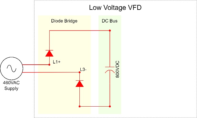
In Figure 1, the diodes shown in red will only conduct when the 3-phase L1 voltage is positive, the L3 voltage is negative, and the difference between the two is greater than the DC bus voltage. At this moment, the charging circuit is simplified to that shown in Figure 2 (the other 4 diodes are not conducting, current flows from L1 to L3). The diodes are arranged to ensure that, as the 3-phase supply voltages alternate from positive to negative, the potential seen at the DC bus terminals is always positive.
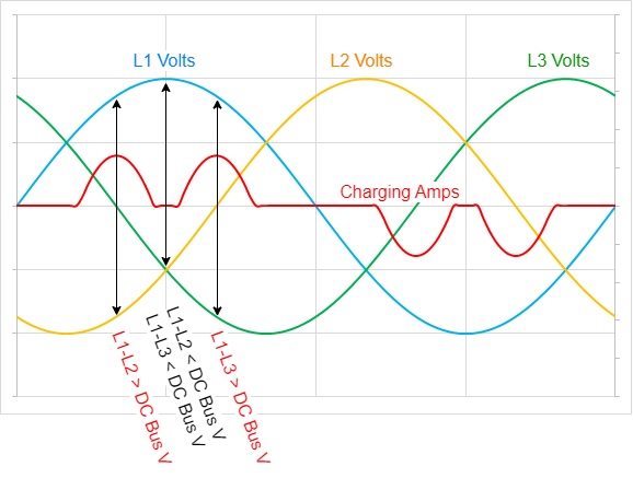
As load is increased, the IGBTs will draw more energy from the bus, which will cause the bus voltage to decrease relative to the supply, and charging current will increase. When loaded, a six-pulse drive will experience six charging pulses in each electrical cycle. The DC bus will charge when:
L1-L2 > Vbus, L1-L3 > Vbus
L2-L1 > Vbus s, L2-L3 > Vbus
L3-L1 > Vbus, L3-L2 > Vbus.
Figure 3 shows the charging current that occurs when the L1 voltage is positive. The first current hump occurs when L1 conducts to L2, the second hump occurs when L1 conducts to L3.
For clarity, only the current influenced by L1 is shown. Including charging current from L2 to L3, and from L3 to L2, a total of six charging events occur in each 60Hz electrical cycle. This is known as a “6 pulse” drive.
Power quality, harmonics, non-linear loads
The application of non-linear loads can cause reliability problems in power distribution systems if not properly mitigated.
Adding a large linear load (such as a resistive heater) to a power system will produce a linear voltage drop. The magnitude of the sinusoidal supply voltage will decrease, but the shape remains sinusoidal.
The addition of a non-linear load, with varying non-sinusoidal current demand, will produce a non-sinusoidal voltage drop on the power system, distorting the voltage waveform of the supply. Distortion of the supply voltage impacts every piece of equipment connected to the supply. In particular, line-connected motors depend on a clean sinusoidal source. Distortion of the supply voltage can negatively impact the operating speed and torque characteristics of all line-connected motors on the system, and result in increased motor heating and reduced efficiency.
Non-linear waveforms are comprised of a large number of harmonic frequencies. The more a waveform is distorted, the greater the amplitude of the harmonic frequencies. Harmonic currents do not reach the motor, and they do not contribute to creating mechanical power. Harmonic currents flow between the power source and the drive, increasing the overall current load on the supply, as well as increasing the I2R losses of the supply transformer, and all wiring between the power source and the drive.
IEEE 519 provides a method to quantify the effects of total harmonic distortion (THD) and establishes thresholds of acceptability. THD is defined as the ratio of the root mean square of the harmonic current to the fundamental current. In other words, it is the ratio of the undesirable current (that does no work), to the desired current (that produces mechanical torque).
Where I1 represents the magnitude of current at the fundamental frequency (that is, 60Hz), and In represents the magnitude of the harmonic current at the nth multiple of the fundamental frequency (that is, I3 = 3rd harmonic = 180Hz), it can be seen that reducing the magnitude of the harmonic content has a direct impact on reducing the severity of current and voltage waveform THD.

Harmonic filtering and how it works
Line reactors are commonly used in low-voltage drive applications to smooth the current waveform. A line reactor is a three-phase inductor installed in series between the supply and the drive. Inductors are components that minimize current fluctuation by storing and releasing energy, essentially shaving energy from the peaks to fill the valleys. Reactors are effective at reducing current distortion (and resultant voltage distortion); however, they cannot eliminate harmonic distortion. The filtered waveform more closely represents the ideal sine wave but remains non-linear. When designing line reactors into a drive system, the additional cost, voltage drop, thermal losses, physical size and weight of the reactors must be considered.
Medium-voltage 36-pulse drive topology
For large motor applications (more than 250HP), multi-Pulse Medium Voltage drives provide an alternate drive topology that improves power quality by minimizing the impacts of harmonic distortion at its source by preventing the formation of highly distorted current waveforms.
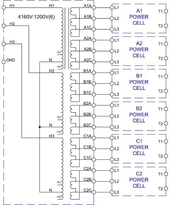
A 36-pulse MV drive uses an isolation transformer with six isolated 3-phase secondaries. Each secondary is phase shifted, creating an 18-phase output waveform. Each phase shifted secondary supplies a drive power cell (each cell with its own 6-pulse bridge as shown in Figure 1).
In the 6-pulse topology, two pulses are generated for each of the 3-phase input waveforms. The current waveform on each supply phase resembles the distorted “rabbit ears” waveform of Figure 6.
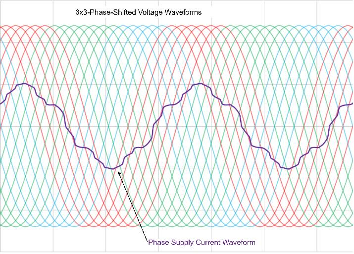
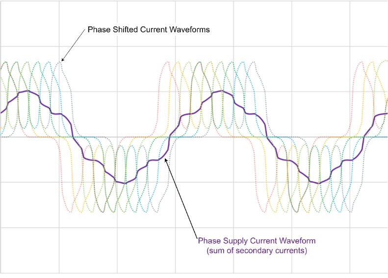
The same principle applies in a 36-pulse topology. Two bus charging pulses are generated for each of the 18-phase voltage input waveforms (Figure 7), for a total of 36 pulses per cycle. More pulses per cycle allow current to be conducted more evenly and continuously throughout the electrical cycle. The supply sees the sum of the 36 secondary charging waveforms. When summed, the 36 “rabbit ear” secondary current waveforms create the nearly sinusoidal supply current waveform shown in Figure 8.
The 36-pulse topology effectively makes the overall drive impedance more constant by ensuring that when one diode switches on, the change in impedance is offset by another diode switching off. The drive load becomes nearly linear, with a nearly-sinusoidal current waveform following the sinusoidal supply voltage.
The measurement of harmonic current distortion provides an objective measure of the relative linearity provided by a 36-pulse system. Without additional filtering or mediation, the percentage of current distortion from a 36-pulse drive can fall well within the limits established by IEEE-519.
Less risk of equipment malfunction, less harmonic stress
Medium voltage drives with 36-pulse topology provide all the benefits common to all variable frequency drives, while inherently reducing harmonic stress on the supply, and minimizing the risk of equipment malfunction or damage from harmonic induced voltage distortion.
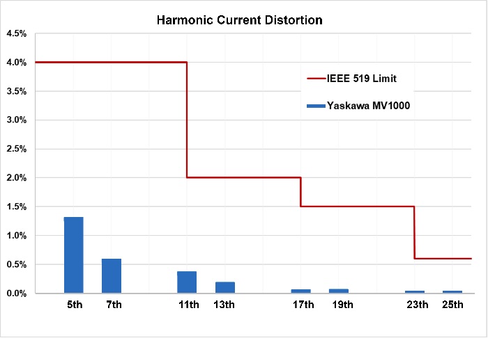
For high power applications, selecting a 36-pulse drive provides an IEEE 519-compliant solution without the need to purchase and install additional input filtering. Because the impacts of harmonics are cumulative within a facility, considering a multi-pulse drive that is well below distortion limits can help compensate for legacy equipment with marginal harmonic characteristics and improve the overall power quality of the facility.
Lucas Paruch is product manager, medium voltage drives, Yaskawa. Edited by Mark T. Hoske, content manager, Control Engineering.
KEYWORDS: Power quality, medium-voltage drives, variable frequency drives, VFDs
CONSIDER THIS
Are your VFDs mitigating harmonics and improving power quality and lifespan for motors?
ONLINE
See part 1 in this series: How to choose a VFD for medium-voltage motors.
https://www.controleng.com/articles/how-to-choose-a-vfd-for-medium-voltage-motors
See more about power quality from Control Engineering.

