With so many control valve options available, it’s important to know how to choose the right body style for a particular application.
Control valve insights
- It’s important to match the various control valve body styles to the right application.
- It’s critical to understand how much of the valve’s throttling range can provide an ideal gain.
- Control valve body styles come in two major categories: sliding stem control valves and rotary valves.
Choosing the right control valve for a specific application can be a daunting task. There is a wide range of body styles with most of these offering a broad selection of body and trim sizes, flow characteristics, packing options and a multitude of body, internal and seal materials.
The details of control valve sizing and the art of material of construction selection is a vast topic. But it’s important to understand the various control valve body styles to help end users make the right choice for their application.
Understanding control valve applications
The first step in valve selection is to fully understand the application. The process conditions will drive the selection of construction material and normal and abnormal flows, and pressure drops will drive the valve sizing calculations, but there are other fundamental requirements that drive selection of the body style itself. Some points to consider include:
- What kind of pressure drops will the valve encounter? Will pressure drop for vapors or gases approach critical flows or sonic velocity? Will liquid processes tend to cavitate or flash through the valve?
- How good is the valve control rangeability or turn down? Must the valve provide control through a wide dynamic range of flows, or will it usually operate within a relatively narrow band?
- What is the required flow characterization of the valve: linear, equal percentage or quick opening? This is generally determined by the requirements of the process being controlled.
- What is the nature of the process fluid and piping arrangement? If the fluid is a slurry or highly viscous or has scaling potential, a different style or valve must be chosen. Similarly, piping requirements like end of line or change in piping orientation will require a different kind of valve.
Before we get into details of selecting a valve type, let’s look at the main valve body styles.
Understanding control valve body styles
Control valve body styles come in two major categories: sliding stem control valves where the stem rises and falls to throttle flow and rotary valves where the shaft turns (usually 90 degrees) to throttle flow. Each style has inherent strengths and limitations that play into valve selection.
Butterfly rotary control valves
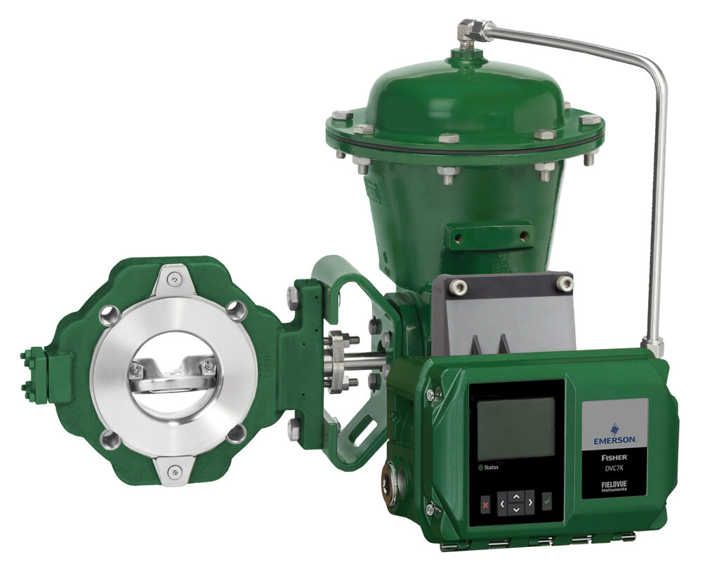
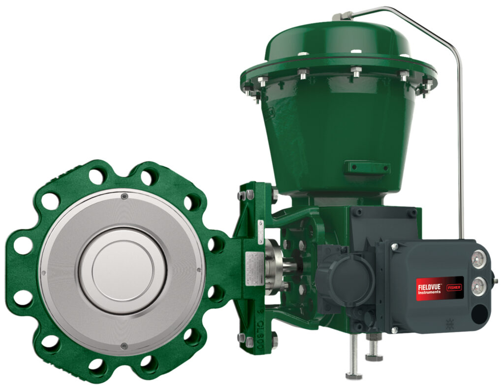
Butterfly control valves use a rotating flat disc to control flow (see Figures 1 and 2). Butterfly valves are the least expensive of the options, owing to their simplistic design, particularly in large sizes. In very large pipe sizes, a butterfly valve may be the only available option.
Butterfly valves may exhibit a linear or equal percentage flow profile depending on the design of the disc and they offer very limited turndown and less control range than the other valve styles. Butterfly valves are also not suited to high pressure drops and flashing and/or cavitation conditions due to the high recovery pressure profile discussed later in this article.
Ball rotary control valves
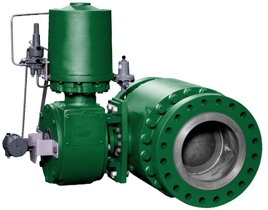
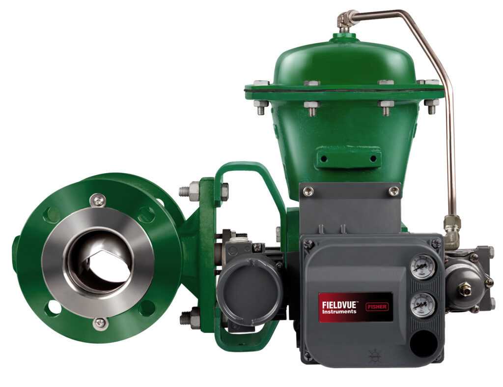
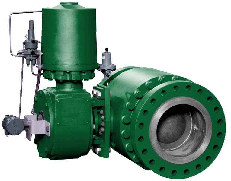
Ball control valves rotate a full ball with a hole or a segment of a ball to throttle flow (see Figures 3 and 4). Ball control valves are offered in full-ported versions to provide an unrestricted and piggable flow path for pipeline applications. Ball valves are typically limited to line sizes up to 24”. Most ball valves have an equal percentage characteristic, though a few models offer linear as an option. Ball valves have limited turndown like butterfly control valves, but some versions do offer anti-cavitation and low noise options not available with butterfly valves.
Like the standard ball valve, the V-ball control valve rotates a ball with a hole in it to throttle flow. It’s offered in full port versions, and it has high noise and cavitation options (see Figure 5). However, the V-ball uses a ball with a V-shaped notch in it to better modulate low flows and to provide significantly higher turndown and better control. The V-notch also enables a shearing action making them suited for pulp and slurries. Line sizes are generally limited to 24” or less. V-ball valves usually have equal percentage characteristics.
Sliding stem control valves
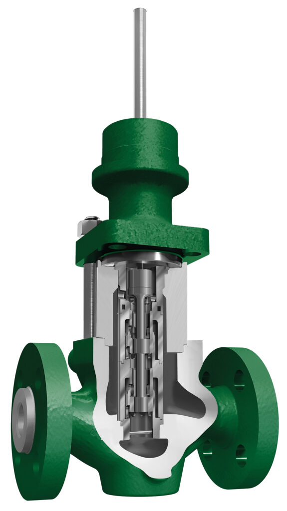
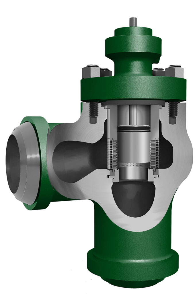
In a sliding stem control valve, the throttling element moves vertically to control the flow of the process fluid. Sliding stem globe control valves come in a vast array of designs with different trim offerings (see Figure 8), allowing a specific model to have quick opening, equal percentage or linear flow characteristics. They often have higher throttling resolution than rotary valves and they have advanced internal designs specifically fabricated to handle very high pressure drops, noise, flashing and cavitation.
However, they have a lower-rated capacity than a comparable rotary design due to the nature of their construction. Sliding stem globe valves are the most complex to manufacture, making them more expensive than other types, but they also offer the most customization options.
What are control valve selection criteria?
Now what we’ve looked at the main control valve body styles, let’s look at some of the selection criteria.
Pressure drops
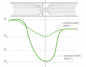
Taking a pressure drop is one of the key functions of a control valve. Even if the inlet and outlet pressures are identical, the internal pressure can differ significantly between sliding stem globe and rotary control valves. Globe valves of all types, including sliding stem, are classified as low recovery. Rotary valves, such as butterfly valves and standard V-balls, are high recovery. As shown in Figure 7, high-recovery valves experience much lower internal pressures, which can lead to issues like cavitation and noise. Consequently, butterfly valves and standard V-balls are not ideal for high-pressure drop applications.
Turndown and control range
From a control valve standpoint, it’s essential to understand how much of the valve’s throttling range can provide an ideal gain. Too little gain can make the control process sluggish, while too much gain can cause the process to swing wildly and potentially lead to system upsets. The gain of a control valve is therefore crucial for effective throttling and maintaining tight control over the process. This refers to how much the flow changes with a change in valve position. Ideally, the gain of the control valve would be 1, but that’s not practical.
EnTech’s Control Valve Dynamic specification recommends a gain between 0.5 and 2 for maintaining good process control.
- A butterfly rotary valve exhibits a significant change in flow area during initial opening, resulting in very high gain and a much lower change in flow area at the top end of its travel range, resulting in very low gain. Therefore, the range where the gain is ideal is limited to the mid-portion of the disc’s travel, typically 25 to 60 degrees.
- This range is better in a ball rotary valve. A V-Ball valve excels in rangeability, offering a wide range of controllable control valve coefficient (Cv) due to significant changes in flow area. However, as a V-Ball reaches the top end of its travel range, the change in flow area diminishes, leading to inefficient throttling capabilities. Therefore, we typically limit the openings of a ball valve to around 70 to 75 degrees for effective throttling. For emergency flow dumps, the valve can open to 80 to 90 degrees.
- A sliding stem valve is characterized by the design of the cage openings or plug contour, offering great flexibility and precision in flow control. The flow area changes and resultant flow rate change can be controlled more precisely, allowing the sliding stem valve to provide a wider throttling range where the gain is optimal.
Understanding sliding stem versus rotary valves
For very large line sizes or basic flow control within a limited dynamic range, a cost-effective butterfly or ball valve is usually sufficient. When improved rangeability is needed, a V-ball valve may be the better choice. Slurry applications are best managed with specially modified V-ball models. For precise control over a broad dynamic range or in cases of very high pressure drops, investing in a sliding stem valve is likely worthwhile.
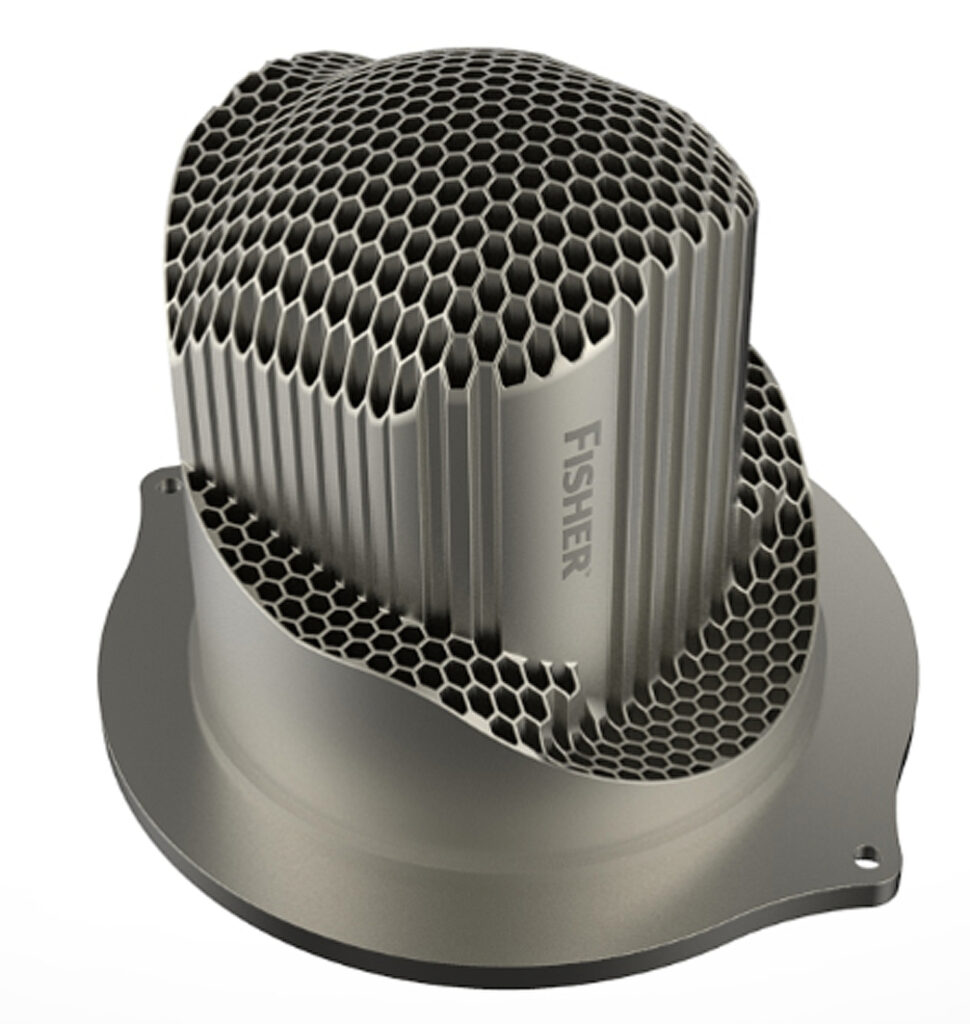
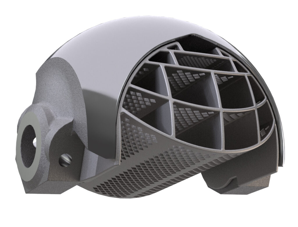
However, a rotary style valve will provide a significant savings, particularly if the application requires only basic flow control. Rotary valve designs generally don’t handle cavitation or high noise conditions well, although recent designs do allow some ball and V-ball valves to incorporate noise and cavitation reduction trims (see Figures 8 and 9).
Other control valve selection considerations
Using a low-quality actuator and/or positioner on a control valve will render the best body style ineffective. A well-designed rotary control valve will instead incorporate an oversized shaft with spline connections to eliminate slippage and backlash.
A quality sliding stem valve will have a stiff stem adequately supported along its length, complemented by a high-quality actuator that is appropriately sized, with a strong spring to ensure reliable control throughout its operating range.
Both body styles should incorporate a high-resolution positioner with tightly coupled or linkage less feedback. For critical applications, users should consider a positioner capable of delivering real-time health status of the valve, adding an extra layer of reliability.
The importance of understanding the capabilities and limits of control valves
The wide range of options can make control valve selection overwhelming. End users must first fully understand the application and its specific requirements. Armed with that knowledge and an understanding of the capabilities and limitations of each valve style, they can choose the right solution for a specific application.
However, there are a broad range of options that can be difficult to negotiate, so spending time discussing specific application requirements and control valve solutions with your control valve partner is a worthwhile endeavor. The valve specification and selection process can be complex, but choosing the right solution will yield big dividends in controllability, process reliability and performance.
TK Arasu is global industry sales manager for Severe Service with Emerson. Edited by Sheri Kasprzak, managing editor, Automation & Controls, WTWH Media, [email protected].
