Tuning a new PID controller begins with an open loop step test. What are the steps? What data do I collect? What calculations are required? How well will it work? What problems might I run into?

PID controller tuning insights
- Learn how to execute an open loop step test and how to estimate the four process parameters required to calculate proposed PID controller tuning constants.
- Know one method to calculate PID controller tuning constants.
- Understand that the calculated PID controller tuning constants may not meet the specific tuning goals for an integrating process; further trimming of the tuning constants may be required.
Open loop, closed loop and heuristic controller tuning methods can be used on integrating processes. There are some differences in each method relative to tuning self-limiting processes. As with self-limiting processes, closed loop tuning isn’t recommended for integrating processes.
What is an integrating process? An integrating process is a process that ramps up or down in response to a change in load or control element value.
Recall that controller gain is independent of vessel size and integral is proportional to vessel size. If true surge control is required, this generally cannot be achieved strictly through PID controller tuning and advanced PID features are required.
We also learned that if an integrating process has some deadtime and/or lags then the controller gain, and integral values may be limited by stability. While this is very rare in refining, it’s not out of the question. Your industry may vary. Should this occur, open loop tuning will yield reasonable results quickly.
Another issue is controller output movement. The output of an integrating process goes somewhere, and a poorly tuned integrating process can amplify incoming oscillations. This will negatively impact downstream operations. Managing controller output movement must be considered when tuning an integrating process.
Open loop tuning method
The open loop controller tuning method is done with the controller in manual mode. This is when an operator manually controls the process output signal.
The method is:
- Place the controller in manual.
- Step the output (OP) up and down 2-10% at least three times; vary the step sizes.
- From trends estimate the
- The change in OP (ΔOP – %)
- The slope of the process variable (PV) before the change (ΔPV/time – %/minute)
- The slope of the PV after the change (ΔPV/time – %/minute)
- The apparent deadtime (Dt – minutes)
- Calculate the process gain (Kp) and from that the vessel fill time (Tfill)
- Calculate the tuning constants using your favorite calculation method
We are assuming the effect of any process lags can be ignored. We are only interested in the effective deadtime any lags create.
How to execute an open loop step test
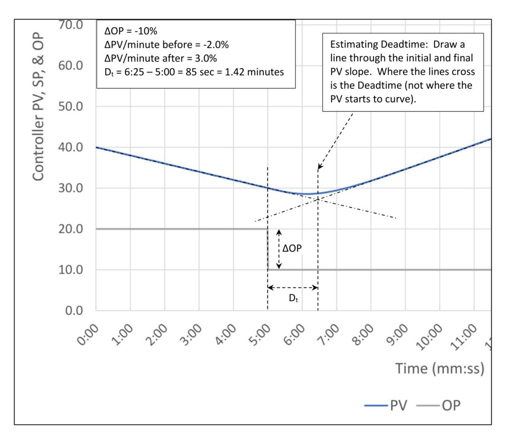
Figure 1 shows a step test for a process with a process gain of 0.5 %/minute, three lags of 30 seconds each and no deadtime.
All open loop tuning methods use this procedure. The only difference is how you calculate the tuning constants once you have the change in controller output (OP), change in process variable (PV) slope (process gain) and deadtime.
Step 1: Place the controller in manual.
Step 2: Verify the PV is moving in a straight line (slope doesn’t matter).
Step 3: Step the controller OP.
Step 4: Estimate the change in PV slope and deadtime from the process reaction curve (read them off the trend).
Step 5: Write down ΔOP, ΔPV/minute before and after the OP step, and the deadtime (Dt).
- ΔOP = -10%
- ΔPV/min before = -2.0%/min
- ΔPV/min after = 3.0%/min
- Dt = 1.42 minutes.
Step 6: Calculate the process gain (Kp) and fill time (Tfill).
Kp = (ΔPV/min before – ΔPV/min after) / ΔOP
Kp = (-2 – 3) / -10
Kp = 0.5 Δ%/min
Tfill = 1/Kp
Tfill = 1/0.5
Tfill = 2.0 min/%
While we are here, we should calculate the fill time/deadtime ratio:
Tfill/Dt = 2.0/1.42 = 1.4:1
This is very close to the bottom of the acceptable fill time/deadtime ratio. We should expect the controller gain to be limited.
Step 7: Calculate and test.
Simplified PI tuning calculations for an integrating process
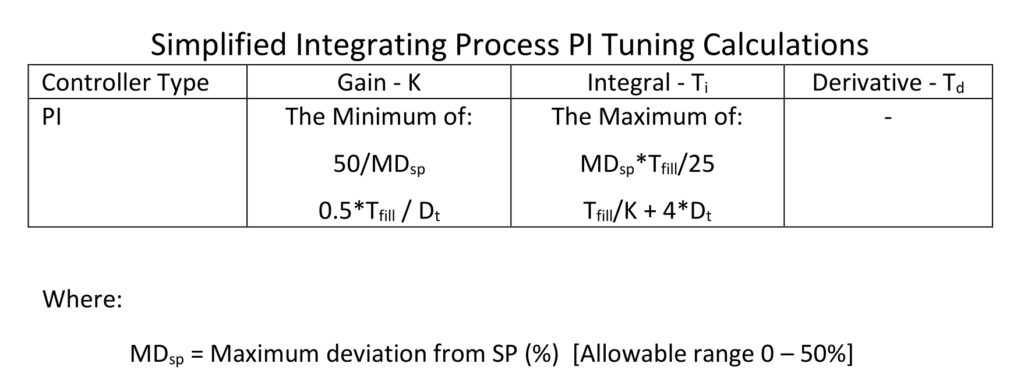
There are several open loop tuning methods for integrating processes. I will start with a version of Fred Thomasson’s simplified level tuning method (“Five Steps to Better PID Control”, Control, p. 65-67, April 1995). Thomasson’s method assumes that process deadtime is zero. This allows him to make use of the fact that controller gain is not affected by process gain and integral is set proportional to process gain. I have added override calculations that will limit controller gain and integral as necessary to maintain stability when the process includes deadtime.
In Thomasson’s method you set the controller gain by estimating how far you are willing to allow the process to wander from setpoint when the input is suddenly stepped to 100%. The assumed starting point is input 50%. This is a crude but effective way to calculate tuning constants that balance process variable movement with controller output movement.
Let’s review the lessons we learned about how PID control works with integrating processes:
1. Absent any apparent deadtime controller gain (K) can be practically unlimited without stability problems.
a. The practical limit on controller gain is how fast and far you are willing to let the controller output move on setpoint changes.
2. Integral must be set proportional to process gain to maintain stability (lower process gain, larger Integral time).
The top calculations (from Thomasson) reflect this knowledge. By leaving it to you to set the maximum deviation from SP he is leaving it to you to set the controller gain.
3. Deadtime will rapidly limit how large controller gain can be while maintaining stability.
4. A lower process gain will permit a larger controller gain while maintaining stability.
5. Integral must be larger (slower) to maintain stability when there is deadtime.
6. A lower process gain requires a larger (slower) integral to maintain stability.
7. A lower controller gain requires a larger (slower) integral to maintain stability.
The lower calculations reflect this knowledge. Regarding the controller gain calculation, if there is no deadtime, controller gain can be unlimited. Deadtime has less effect on the controller gain as the process gain gets smaller. Regarding integral, the presence of deadtime requires a larger (slower) integral. Both larger controller gain and process gain allows a smaller (faster) integral. The various constants were developed by testing against a process model. In short, there is some wiggle room to set these to something you might like better.
Example calculation 1
Since we step tested a process with a fill time of 2.0 minute/% and three 30-second lags, resulting in an apparent deadtime of 1.42 minutes, let’s see how the calculations turn out.

The calculated controller gain is the lower of 2.5 and 0.70. The lower controller gain calculation is telling us that this process will have stability problems at a higher controller gain as we expected from the fill time/deadtime ratio. The calculated integral is the higher of 1.6 and 8.5.
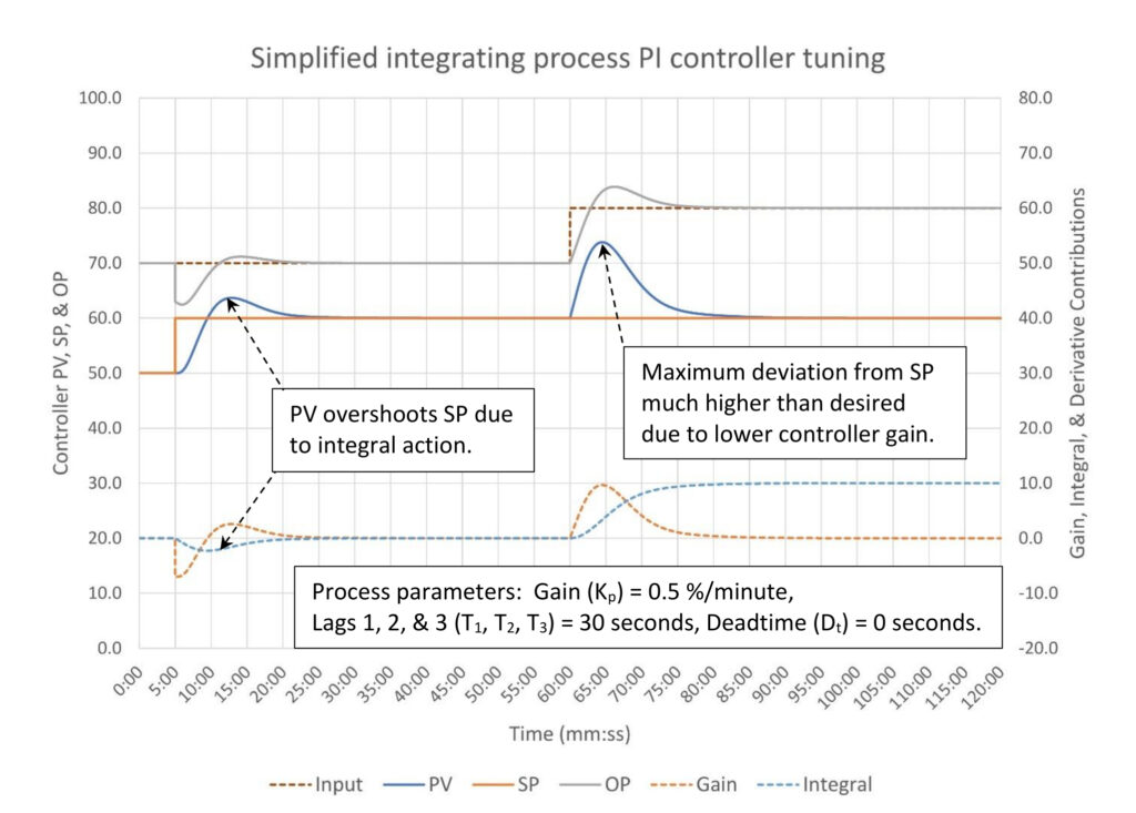
In Figure 2, the process variable’s maximum deviation from setpoint is much larger than the 4.0% we would have expected from a controller gain of 2.5. The alternate tuning is stable. A controller gain of 2.5 and integral of 1.6 is unstable. Also as expected the quick integral action results in the process variable overshooting the setpoint after a setpoint change. Recovery from an input flow disturbance is close to ideal disturbance rejection tuning. If something closer to surge control tuning is desired, the integral should be slowed down.
Example calculation 2
To check the effectiveness of Thomasson’s calculations, set the deadtime to zero.

The controller gain is now 2.5 and the integral is 1.6.
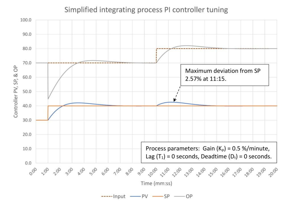
In Figure 3, the process variable’s maximum deviation from setpoint is 2.57%, much less than would be expected from controller gain action alone. The addition of integral has reduced the maximum deviation.
The higher controller gain has resulted in a very large jump in controller output when the setpoint is changed. If this is an issue, consider using some form of setpoint processing to limit the severity of the response.
Finally, eliminating the deadtime resulted in a large drop in the time it takes to restore the process variable to setpoint after a disturbance; 4.5 minutes without deadtime versus 25 minutes when there is 1.4 minutes of deadtime. Time off setpoint can be pushed under 2 minutes if true disturbance rejection tuning is applied. Even a little bit of deadtime has a large impact on how well a PI controller can control an integrating process.
Example calculation 3
Let’s see how a bigger vessel (lower process gain) affects controller tuning. The new process gain (Kp) is 0.1 %/minute (Tfill = 10 minutes/%) with three 30-second lags and no deadtime. Lowering the process gain increased the apparent deadtime from the three lags to 1.6 minutes. Based on this the tuning constants are:
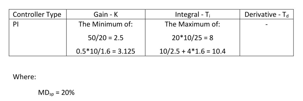
This results in tuning constants of K = 2.5 and Ti = 10.4. Note that controller gain comes from the top calculation set and the integral comes from the bottom calculation set. This is unusual but works just fine.
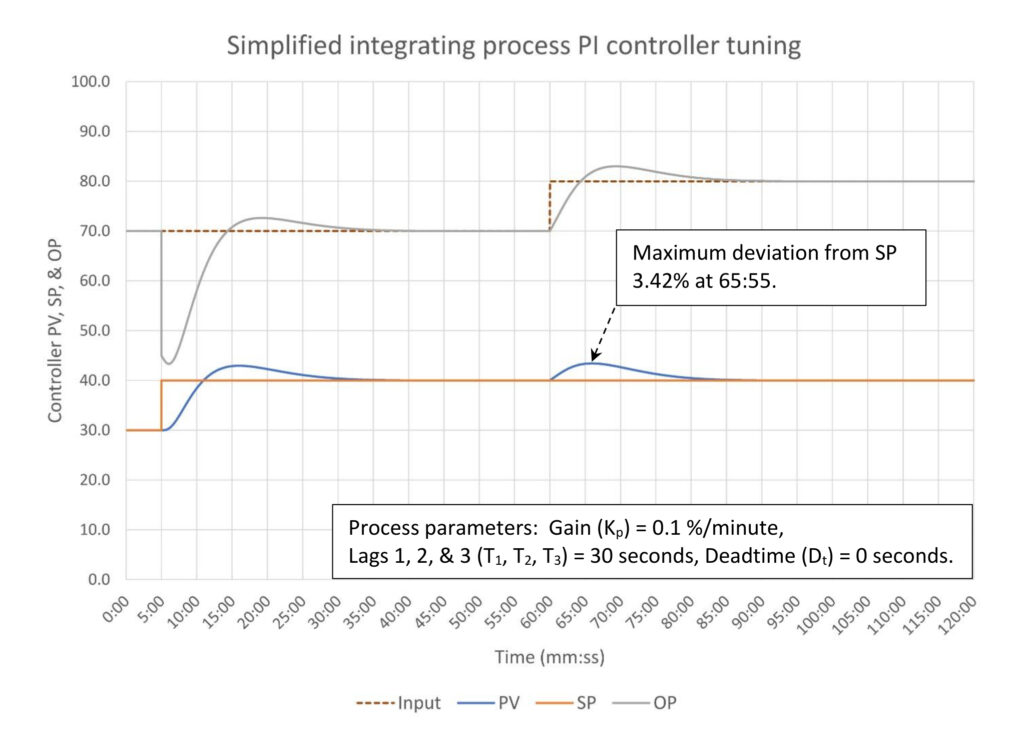
In figure 4, relative to example 1, increasing the vessel size by a factor of five (reducing the process gain from 0.5 to 0.1 %/minute) allowed us to maximize the controller gain to 2.5 from 0.7, which reduced the maximum process variable deviation from setpoint after a disturbance from 14% down to 3.4%. As expected, the controller output makes a much larger step when the setpoint is changed.
The adequacy of a simplified loop tuning calculation
If refining vessels are uniformly large, real deadtime is almost nonexistent, and process lags are generally small as they are usually limited to the response speed of a cascade secondary flow controller.
Thomasson’s simplified loop tuning calculations will generally be adequate for just about all level controllers. You can usually estimate process gain from vessel drawings or even the information available on a P&ID, often eliminating the need to do step testing.
Open loop tuning tips
Make multiple steps when performing the open loop test (minimum of three). The step sizes should be different sizes and be made in opposite directions. This is necessary to see if the valve is working. A cascade master may not require multiple steps as valve performance should not be a problem.
The limitations of open loop tuning
Bad valves will warp the results. Estimated process gain can be wildly inaccurate, especially with small step sizes. Deadtime may also appear variable based on valve response.
As a matter of good practice before you tune an existing control loop you should check the loop for valve problems and other non-loop tuning related problems. Control tuning doesn’t just go bad; something has happened to a piece of equipment somewhere to cause the problem.
Open loop testing to estimate controller tuning constants
Open loop testing is a straightforward method to estimate controller tuning constants. Unlike self-limiting processes step testing of an integrating process should proceed quickly as we are only interested in the seeing the PV change direction. You don’t need to wait for a final process gain.
A highly simplified method based on Fred Thomasson’s work was modified to accommodate process deadtime. This will provide adequate control but makes no attempt at surge control, nor does it try to balance PV deviation against OP movement. Issues can be addressed through advanced PID features and/or non-linear PID (or other) control algorithms.
Variables, most commonly bad valves, can contaminate the open loop test results. This will result in calculating bad tuning constants.
Ed Bullerdiek is a retired control engineer with 37 years of process control experience in petroleum refining and oil production. Edited by Mark T. Hoske, editor-in-chief, Control Engineering, WTWH Media, [email protected].
CONSIDER THIS
How does open loop tuning of an integrating process differ from that of self-limiting processes and how do the calculations differ? What new possible issues need to be considered when tuning an integrating process?
ONLINE
PID series from Ed Bullerdiek, retired control engineer
PID spotlight, part 1: Three reasons to tune control loops: Safety, profit, energy efficiency
PID spotlight, part 2: Know these 13 terms, interactions
PID spotlight, part 3: How to select one of four process responses
PID spotlight, part 4: How to balance PID control for a self-limiting process
PID spotlight, part 5: What does good and bad controller tuning look like?
PID spotlight, part 6: Deadtime? How to boost controller performance anyway
PID spotlight, part 7: Open loop tuning of a self-limiting process
PID spotlight, part 8: Closed loop tuning for self-limiting processes
PID spotlight, part 9: Heuristic tuning for a self-limiting process (part A on heuristic tuning)
PID spotlight, part 10: Heuristic tuning in a self-limiting process
PID spotlight, part 11: How a PID controller works with an integrating process
PID spotlight, part 12: What does good and bad controller tuning look like?
PID spotlight, part 13: Deadtime: what’s the best that I can do?
Aug. 1 RCEP webcast available for one year: How to automate series: The mechanics of loop tuning
More on PID and advanced process control from Control Engineering.
